Damage Stability of Tankers
The fifty-third session of the IMO's Sub-Committee on Stability and Load Lines, which met in the second week of January 2011, discussed the long running issue of damage stability of tankers.
A paper had been submitted by OCIMF and SIGTTO providing a draft text of operational Guidance for onboard verification of damage stability prior to sailing. IPTA had co-sponsored a document supporting in principle the content of the document but pointing out that there is currently no requirement under IMO regulations for approval of damage stability software and it would therefore be inappropriate to include such a requirement in IMO Guidance. This document received support from a number of delegations and will be taken into account in the ongoing discussions.
It was agreed that further discussions are needed on a number of issues and that it may be necessary to make amendments to some mandatory instruments before guidance be can be finalised, and to this end a correspondence group was established which will report back to the next session of the Sub-Committee in 2012.
The instructions given to the correspondence group are as follows:
identify existing IMO instruments and relevant references relating to the issue of verification of damage stability requirements ;
.2 identify any ambiguities in the existing requirements and consider the need for clarifications and/or recommendations for amendments to mandatory instruments;
.3 develop draft Guidelines for the verification of damage stability requirements for tankers, addressing design and operational issues.
.4 consider whether demonstration of verification to third parties (Port State Control) should be addressed in the draft Guidelines and, if so, include appropriate text;
.5 consider, when developing the above draft Guidelines, in particular the following points:
.1 scope of the draft Guidelines;
.2 clarification of what is meant by “loaded in accordance with” an approved condition, whether any deviations are allowed and, if so, to what extent;
.3 methods of verification of compliance, such as stability software, stability booklet, shore assistance, KG/GM curves and conditions for use of these methods; and
.4 clarification of the terms and conditions for use of stability software and documentation which demonstrates that the software is appropriate for its purpose;
Some intense discussion is anticipated on the definition of what constitutes an “approved condition”, since some delegates insist that this means the vessel must be loaded exactly in accordance with one or other of the conditions in its stability book, while others are of the opinion that this is totally impractical. A number of delegates were also of the opinion that the use of GM/KG curves for verification is inappropriate for chemical/parcel tankers and that damage stability computers should be mandatory for such ships. If such a regulation were to be mandated functional requirements would need to be developed for the software.
To Calculate Damage Stability, without the help of softwares, please see the following:
ARCHIMEDES PRINCIPLE:
 When an object is immersed in water, it feels lighter. In a cylinder filled with water, the action of inserting a mass in the liquid causes it to displace upward. In 212 B.C., the Greek scientist Archimedes discovered the following principle: an object is immersed in a fluid is buoyed up by a force equal to the weight of the fluid displaced by the object. This became known as Archimedes principle. The weight of the displaced fluid can be found mathematically.
 The fluid displaced has a weight W = mg.
The mass can now be expressed in terms of the density and its volume, m = pV. Hence, W = pVg.
BUOYANCY:
If a cubic centimeter of aluminium was suspended in a fluid such as water with a very thin and negligible thread, the metal cube would have the fluid exerting pressure on the cube. Try to imagine that if the cube were to disappear, and the fluid would magically replace the cube, then the surrounding water would support this cube that is now containing water, so that the cube of water would be motionless. That is, the forces would be balanced. The cube of water would push out on the surrounding water and the surrounding water would push back on the cube. The fluid would be static, or stationary. Now replace this same cube of water with the original cube of aluminium. The surrounding water would not 'know' that the cube has been replaced with another substance. It would still push inward and upward and downward with the same force that it pushed on the cube of water. The sideways forces would be balanced and oppose each other equally, but the upward and downward forces would not be the same. The pressure at the bottom of the cube is greater than the pressure at the top of the cube, because pressure increases with increased depth. The difference between the upward and downward forces acting on the bottom and the top of the cube, respectively,is called buoyancy.
Using the aluminium as our example, it has a specific gravity of 2.8. Water has a specific gravity of 1.0. This means that a cubic centimeter of water would have a mass of 1.0 grams, while aluminium of the same size would have a mass of 2.8 grams. Since the aluminium cube displaces 1 cubic centimeter of water, it has a buoyancy of 1.0 grams. Since buoyancy is a force and not a mass, it must be converted to the proper units, which when multiplied by the acceleration of gravity (980 cm/s2) gives the units of dynes. That is,
(1.0 grams) (980 cm/s2) = 980 grams cm /s2 or dynes
So our aluminium cube immersed in water would not 'weigh' (2.8 x 980) dynes or 2744 dynes. It would weigh less due to the fact it has a buoyant force of (1 x 980) dynes from the water. So it would weigh (2744-980) dynes or 1764 dynes while immersed in the water.
The Buoyancy Principle
Archimedes continued to do more experiments and came up with a buoyancy principle, that a ship will float when the weight of the water it displaces equals the weight of the ship and anything will float if it is shaped to displace its own weight of water before it reaches the point where it will submerge.
This is kind of a technical way of looking at it. A ship that is launched sinks into the sea until the weight of the water it displaces is equal to its own weight. As the ship is loaded, it sinks deeper, displacing more water, and so the magnitude of the buoyant force continuously matches the weight of the ship and its cargo.
The Metacenter
 Archimedes figured out that the metacenter had to be determined which is a point where an imaginary vertical line (through the center of buoyancy) intersects another imaginary vertical line (through a new centre of buoyancy) created after the ship is displaced, or tilted, in the water.
The center of buoyancy in a floating ship is the point in which all the body parts exactly balance each other and make each other float. In other words, the metacenter remains directly above the center of buoyancy regardless of the tilt of the floating ship. When a ship tilts, one side displaces more water than the other side, and the center of buoyancy moves and is no longer directly under the center of gravity; but regardless of the amount of the tilt, the center of buoyancy remains directly below the metacenter. If the metacenter is above the center of gravity, buoyancy restores stability when the ship tilts. If the metacenter is below the center of gravity, the boat is unstable and capsizes.
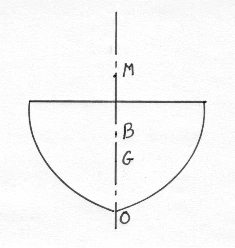
The ship, loaded down to her marks, is lying in still water without list.
WL = Water line
G = Center of Gravity
B = Center of Buoyancy of water displaced by the ship
G and B are lying in the same vertical plane amidships. The ship is in stable equilibrium. The upward pressure acting through B is equal to the weight of the ship acting downward through G.
 Centre Of Buoyancy And Stability
The Buoyancy Force act through the Centre of Gravity of the Displaced Fluid and is called " The Centre of Buoyancy"
There are three Types of Equilibrium.
· Stable. The body returns to it's original position if given a small angular displacement.
· Neutral. The body remains in a new position if given a small angular displacement.
· Unstable. The body heals further over if given a small angular displacement.
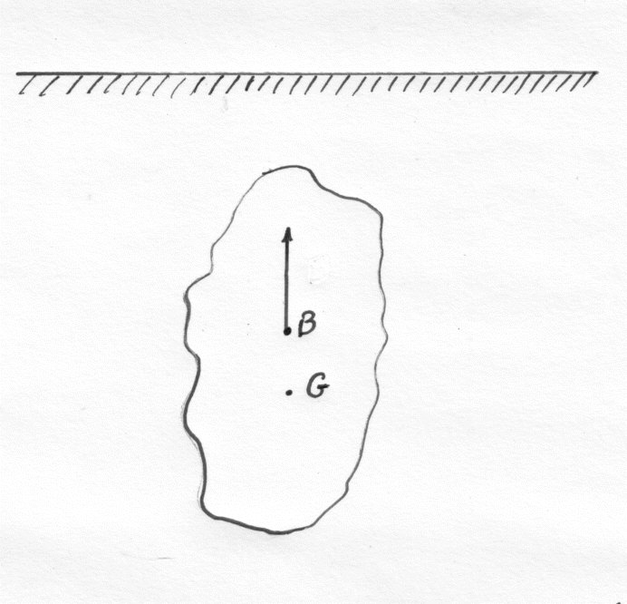
 The Stability Of Fully Submerged Bodies
Let
· V = Volume of Body.
· w = Specific weight of the fluid.
· W = Weight of the Body.
· G is the Centre of Gravity.
·  B is the Centre of Buoyancy and is the centre of gravity of the displaced liquid.
 B is the Centre of Buoyancy and is the centre of gravity of the displaced liquid.
If B and G are coincident the the Body will be in Neutral Equilibrium.
B is below G then the Body is in Unstable equilibrium.
B is above G then the body is in Stable equilibrium.
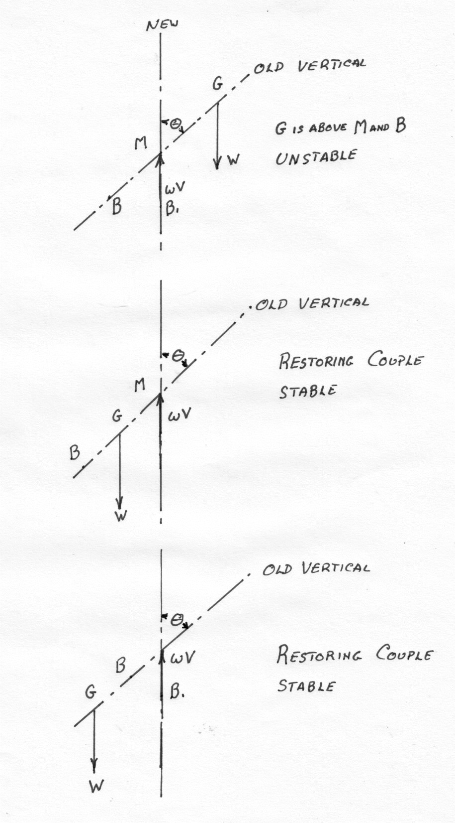 This last case has a righting couple of WBG sinθ Where θ is the angle of tilt. Note that the Position of B and G relative to the Body does not change when the body is rotated.
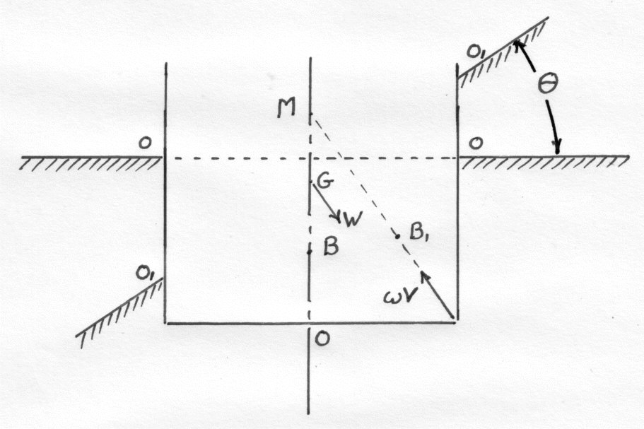
The Stability Of Partially Submerged Bodies
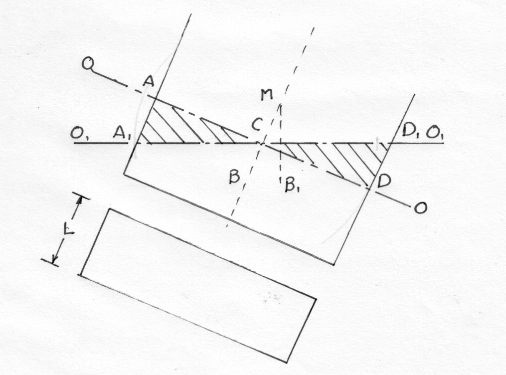
G is the C of G. B is the C. of B and The line “O-O” is the original water surface.
After tilting “O1- O1” is the new water line and the angle of Tilt is θ
G remains in the same position relative to the ship but the Centre of Buoyancy moves to B1
M is the "META CENTRE" and is defined as the point where the vertical through the new Centre of Buoyancy meets the original vertical through the Centre of Gravity after a very small angle of rotation.
MG is called the METACENTRIC HEIGHT
Therefore for stable equilibrium for a floating Partially Submerged Body the Meta centre must be above the Centre of Gravity G. If the Metacentric height is zero the Body will be in Neutral equilibrium.
In ship design the choice of the Metacentric height is a compromise between stability and the amount that the ship rolls. In British Dreadnaught Battle ships, for instanace, the metacentric height was so great that they had a tendency to roll badly, even with large bilge keels.
The Righting couple = WGM sinθ
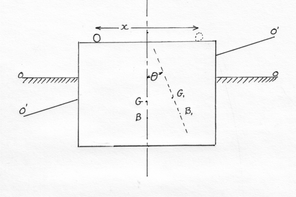
1) Experimentally
Let W be the weight of the Ship plus it's Load
A small load w is moved a distance x and causes a tilt of angle. The Ship is now in a new position of equilibrium with B' and G' lying along the Vertical through M.
The Moment due to the movement of the load is given by:-
Wx = W x GMθ = moment due to movement of C of G
Therefore, GM = wx / Wθ
The Ship tilts from it's old waterline OO to a new waterline O1 O1 as it moves through an angle θ. Due to the movement of the wedge of water from A1A C to D1 D
C, the Centre of Buoyancy moves from B to B1
The Change in the moment of the buoyancy Force = wV X B B1
(3)
= wV x BMθ where θ is small
The Volume of the Wedge A C A'
Therefore the Moment of the Couple due to the movement of the wedge is [ 2w2b3Lθ / 24 ]
Thus
Where I is the Second Moment of Area of the Water Plane Section and V is the volume of water Displaced.
Thus if the positions of B and G are known or can be calculated , then the distance GM can be determined since:-
GM = BM + BG = Bm + BO - OG
There are in fact two Metacentric heights of a ship. One for Rolling and the other for Pitching. The former will always be less than the latter and unless otherwise stated, the Metacentric given will be for Rolling.
DAMAGED SHIP:
CHANGE IN DRAUGHT (DRAFT):

 When a ship has one or more damaged compartments, the draft will increase to compensate the loss of buoyancy from the damaged compartments. A new equilibrium is reached to account for this and the ship submerges proportionately.
 HEELING ANGLE
If the damage is unsymmetrical around the centerline of the ship, the ship will develop a heeling moment, and heel towards one side, basis the shift of transverse centre of buoyancy.

CHANGE OF TRIM
 If the damaged compartments are away from the center of buoyancy, a lever is caused to change the trim of the vessel in the fore and aft direction, which may be significant, basis the position of the damaged compartment
The basic property of the fluids is freedom of motion, which is also called entropy in physical sense, or randomness in the general sense.
 Consider this and understand, how the sea water would behave in turn with a damaged compartment. They will practically assume that the compartment is non-existent for a damage.
(A resultant behavior would also be the sea trying to exert hydrostatic pressure and gushing in to fill up the space. On the contrary, if the compartment is filled up, the contents may venture out or mix with water as per their physical & chemical properties.
This is a separate subject and has to be taken into account, basis the cargo / product / chemical in the ship’s damaged tanks / holds.
 CENTRE OF GRAVITY, G & CENTRE OF BUOYANCY, B
 The stability of the ship is affected by the damage, as explained above. The under water hull is completely different and therefore the stability parameters are bound to change in the same proportions. If the cargo in the compartments are still on board the ship, after the damage, the Centre of Gravity G will remain at its original position with respect to the horizontal, vertical and transverse axes. However, the position of the Centre of Buoyancy will change its position in such a way that the final equilibrium position, in which ship would lie in a calm sea, such that B & G would lie in the same vertical line in any of the axes. The ship in turn would tilt around that axis, or the combination of axes towards which the B has shifted.
 METACENTRIC HEIGHT, BM

 The metacenter, M will change location since the shape of the under water hull (or the water displaced by it) has changed. The metacentric height GM, will often decrease, but can in fact sometimes increase, depending on the width of the damage. The location of M depends on the displacement of the ship and the moment of inertia of the water plane area around a longitudinal axis through the centre of floatation by the formula:
BM = Moment of Inertia / Displacement, Where BM is the metacentric height.
 DAMAGE EXTENDING ABOVE ORIGINAL WATERLINE:
 If the damaged compartments extend above the waterline, they will cut a hole in the water plane area and reduce the moment of inertia.
Since the displacement is constant, BM will be reduced. The center of buoyancy B will rise due to increased draught, but not so much as decrease in the BM. This means that center of gravity G will be closer to M after the damage and the ship will have a smaller GM.
DAMAGE NOT REACING THE ORIGINAL WATERLINE:

 If the damage only affects, for example the double bottom spaces, the water plane area will be almost unaffected. A little increase of draught gives larger waterplane area and a slightly increased moment of inertia.
This means that the distance BM will increase and increased draught will push B upwards and consequently GM will increase.
 VOLUME PERMEABILITY COEFFICIENTS:
The damaged compartment in the ship can not be completely filled with sea-water because interior outfitting, machinery or cargo already occupies the compartment. The permeability of the space is expressed with a decimal figure that is the maximal volume of water that can enter the compartment divided with the total volume of the compartment. This figure is used to estimate how many tones of sea water that can enter the ship in case of a damage, which is used for calculating the new floating position.
Related regulation: MSC.Res.216(82), Reg. 7-3
For the purpose of the subdivision and damage stability calculations of the regulations, the permeability of each general compartment or part of a compartment shall be as follows:
| SPACE | PERMEABILITY |
| Appropriated to stores | 0.60 |
| Occupied by accommodation | 0.95 |
| Occupied by machinery | 0.85 |
| Void spaces | 0.95 |
| Intended for liquids | 0 or 0.95, whichever results in more severe requirement |
Variable permeabilities for cargo spaces are newly implemented (in SOLAS 2004 fixed permeabilities are stipulated). The permeabilities depend on the considered draught (deepest subdivision / partial subdivision / light service) and on the type of cargo space (dry cargo / container / ro-ro / liquid cargo).
For the purpose of the subdivision and damage stability calculations of the regulations, the permeability of each cargo compartment or part of a compartment shall be as follows:
| SPACE | SUBDIVISION DRAFT | PARTIAL DRAFT | LIGHT SERVICE DRAFT |
| Dry Cargo Spaces | 0.70 | 0.80 | 0.95 |
| Container Spaces | 0.70 | 0.80 | 0.95 |
| Ro-ro spaces | 0.90 | 0.90 | 0.95 |
| Cargo Liquids | 0.70 | 0.80 | 0.95 |
| Timber cargo in holds | 0.35 | 0.70 | 0.95 |
THERE ARE TWO MAIN METHODS USED GENERALLY TO CALCULATE DAMAGE STABILITY.
1) LOSS OF BUOYANCY METHOD
2) ADDED WEIGHT METHOD
Below, description is given for both systems.
 LOSS OF BUOYANCY METHOD:
In the loss of Buoyancy method, which is really the true method, or a more closer representation of judging damage stability, the ship will have a new under water hull form, and a new equilibrium is calculated based on this.
Calculation Procedure:
When calculating the floating position and stability after damage with Loss of Buoyancy method, the following procedure should be followed.
1.  Calculate the volume of the flooded sea water, i.e., the loss of buoyancy, by multiplying the displacement (for the original water line of the damaged compartment) with the volume permeability of the compartment.
Calculate the volume of the flooded sea water, i.e., the loss of buoyancy, by multiplying the displacement (for the original water line of the damaged compartment) with the volume permeability of the compartment.2.  Calculate the change in draught and the new location of the longitudinal center of floatation, LCF, and the transverse center of Floatation, TCF for the remaining water line area, when damaged compartments arew taken away.
Calculate the change in draught and the new location of the longitudinal center of floatation, LCF, and the transverse center of Floatation, TCF for the remaining water line area, when damaged compartments arew taken away.
3. Calculate moment of inertia for the remaining water line area based on the new center of floatation, both transverse and longitudinal. Thereafter calculate the new BM.

4.  Calculate the new location of the centre of Buoyancy B, above the keel (distance from keel).
Calculate the new location of the centre of Buoyancy B, above the keel (distance from keel).5. Calculate the new GM.
6. 
 Calculate the heeling angle and trim in damaged condition.
Calculate the heeling angle and trim in damaged condition. Correction of GZ Curve:
The true GZ for the actual damage can be calculated only if the cross curves, KN values are calculated for the damaged hull.


Note:
The loss of Buoyancy Method is true representation of damage stability, is more accurate, however, is not a recommended method, when carrying out the calculations manually. This method is more suitable for programming on computers. If Masters are capable of making an excel sheet which can do this, it is worth being considered. However, in all other cases of manual calculation, the more preferred method used is Added Weight Method.


 When calculating the floating position and stability after damage with Added Weight Method, the following procedure should be followed:
1.  Estimate the mass of the flooded seawater and use this as an added weight.
Estimate the mass of the flooded seawater and use this as an added weight.2. The new draught and displacement for the ship is calculated based on this added weight.
3.  Estimate the location of the Center of Gravity g of the flooded seawater and calculate the effect on the center of gravity of the ship G.
Estimate the location of the Center of Gravity g of the flooded seawater and calculate the effect on the center of gravity of the ship G.4. Calculate the new GM for the new draught and the location of G.
5. Calculate the effect of free surface, since the added weight is a liquid, and reduce GM by the formula:

 GGv = (I/D) + [(A-y2)/D],
Where:
GGv is the virtual rise of G due to free surface effect.
I is the moment of inertia of the free liquid surface in the damaged compartment
D is the displacement of the ship in cubic meters
A is the area of the free surface
 y is the distance between the centerline of the ship and centre of free surface area of sea water in the compartment.
The term: (A-y2)/D is a contribution from Steiner’s theorem of Free communication effect of the water in the damaged compartment. Notice that if the damage is symmetrical around the centre line of the ship, this term does not exist in ordinary free surface corrections from tanks, since the tanks have no free communication with the sea.
6.  Calculate new trim and list.
Calculate new trim and list.When the new floating position has been calculated, it is possible to check if the water level in the damaged compartment corresponds to the estimated volume of the flooded sea water. If not, the procedure should be started all over again and a new estimation of flooded water, that is added weight should be made.
Correction of GZ Curve:
 A new GZ curve should be calculated according to the new location of G and floating position of the ship. This curve should then be corrected for heel, cosines correction, free surface effect of the flooded water, sine correction and possible communication effect, again a sine correction.
Watertight:
 Watertight capable of preventing ingress of water during static submersion under a head of water for which the surrounding structure is designed. A watertight closing appliance is also considered weathertight.
Weathertight:
 Weathertight means that in any sea condition water will not penetrate into the ship.
Watertight bulkhead:
A watertight bulkhead is a longitudinal or transversal bulkhead extending from double bottom to bulkhead deck.
Margin line:
The margin line is an assumed line 3 inches or 76mm below the bulkhead deck of the ship.
DEFINITIONS:
Subdivision load line:
“Subdivision load line” is a water-line used in determining the subdivision of the ship. “Deepest sub-division load line” is the water line which corresponds to the greatest draught permitted by the applicable subdivision requirement.
Internal Watertight integrity:
The capability of internal structures and their closing appliances to prevent progressive flooding to volumes assumed buoyant or intact. The internal watertight integrity includes position and type of closing appliance, alarms, indicators, remote controls and signboards fitted to such appliances. Further, watertight closing of pipes, ducts and tunnels in the damage penetration zone is regarded as a part of the internal watertight integrity.
Progressive flooding:
Ingress of water through internal openings to compartments assumed to be intact.
Downflooding angle related to intact stability:
The minimum heel angle where an external opening without weathertight closing appliance is submerged.
Damage zone:
The minimum heel angle where an external opening without water-tight closing appliance is submerged.
Residual stability:
The positive range of the righting lever curve, GZ, after damage, with external heeling levers taken into account.
MEASURES IN CASE OF DAMAGE:
·  Close all watertight doors, if applicable
Close all watertight doors, if applicable· Be sure all openings on free board deck are closed
· Reduce heeling angle by heeling tanks or ballast tanks
· Be sure that the valves in those pipes which come from the damaged compartments are closed.
· Close the valves of scuppers that go through the damaged compartments.
· Inform SUNCE, in order to activate the office ERT.
· Activate Emergency Response Services (SERS), if agreement is in place. (Always ensure the contact details of the same is available close to communication equipment)
· Inform other concerned parties.
· Check soundings of all tanks, assess damage.
· Damage control – would ideally include transfer of cargoes, if possible, minimize pollution, if a threat, reduce or neglify list (When you do this, be sure of the ship’s fluid GM not becoming negative, else the vessel will go to unstable equilibrium and in bad weather the vessel can topple / capsize).
· Take guidance from office, if unsure. We are to work as a team.
most of times charterers requires up to full cargo capacitiy and masters are planning according to limitations of the vessel and the company procedures (probably %98) but at some of damage case(s) are not met in fully condition and it will not give a chance to revise the plan due to full of cargo. What Master shall do?
ReplyDelete